K-Style Gutter Installation: Field Specification Guide
K-Style Gutter Installation is a foundational field competency requiring precise dimensional control across four interdependent mechanical systems: pitch geometry, hanger load distribution, downspout hydraulic sizing, and miter joint fabrication.
Deviation in any one system propagates structural failure across the remaining three. The following specification governs 6-inch K-Style Gutter Installation on standard residential fascia substrates per SMACNA Architectural Sheet Metal Manual standards.
Key Takeaways
- **Pitch Geometry Baseline:** A minimum vertical drop of 1/4 inch per 10 linear feet of horizontal run is non-negotiable for proper water velocity and drainage.
- **Structural Load Distribution:** Hanger spacing at 24 inches on center serves as the structural baseline, dropping to 18 inches on center in high snow-load regions.
- **Joint Integrity Requirements:** Strip miter fabrication requires a clean, completely degreased aluminum surface and high-grade polyurethane sealant rather than standard silicone.
- **Hydraulic Evacuation Capacity:** Rectangular 3×4-inch downspouts manage significantly more hydraulic volume than 2×3-inch downspouts and should be specified as the default on any drainage run exceeding 35 linear feet.
- **Precision Fabrication Tools:** Cutting accurate inside and outside miter joints requires calibrated offset aviation snips used in conjunction with a fixed miter template or geometric angle finder.
Section 1 — Pitch Geometry and Layout Math
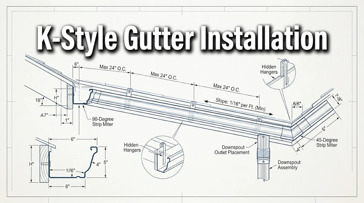
The minimum drainage slope for a residential K-style gutter installation run is 1/4 inch of vertical drop per 10 linear feet of horizontal run, directed toward the downspout outlet. This slope produces a flow velocity sufficient to carry shingle grit and fine particulate through the outlet tube without sediment accumulation at the low point.
On runs exceeding 40 linear feet, a single-slope layout produces a visible pitch differential detectable from grade level. Runs over 40 feet require a dual-slope configuration: pitch from both ends toward a center outlet, or from a center high point toward outlets at each end. The chalk line snap establishing the pitch baseline must be set before the first hanger is installed.
| Run Length (ft) | Total Drop Required (in) | Slope Configuration | Outlet Count |
|---|---|---|---|
| 0 – 20 | 0.5 | Single slope | 1 |
| 21 – 40 | 0.5 – 1.0 | Single slope | 1 |
| 41 – 60 | 1.0 – 1.5 | Dual slope recommended | 2 |
| 61 – 80 | 1.5 – 2.0 | Dual slope required | 2 |
| 80+ | 2.0+ | Dual slope with center high point | 2 minimum |
Section 2 — Hanger Load Distribution and Fastener Specification
Hidden screw-in hangers are the current field standard for 6-inch K-style gutter installations of seamless aluminum. Spike-and-ferrule fasteners are mechanically inadequate for long-term load retention under thermal cycling and ice loading conditions and are excluded from this specification.
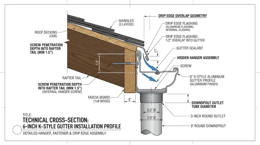
Standard hanger spacing is 24 inches on center for residential applications in temperate climates. In ASCE 7 ground snow load zones exceeding 25 psf, spacing reduces to 18 inches on center to maintain structural integrity under ice loading. Each hanger drives a minimum #10 x 1-1/2 inch hex-head screw into sound fascia substrate with a minimum embedment depth of 1-1/4 inches into the rafter tail or structural backing.
| Climate Zone | Ground Snow Load | Hanger Spacing (OC) | Minimum Screw Spec |
|---|---|---|---|
| Temperate (Zones 1–3) | 0 – 25 psf | 24 inches | #10 x 1-1/2 in hex-head |
| Transitional (Zones 4–5) | 25 – 50 psf | 18 – 20 inches | #10 x 1-1/2 in hex-head |
| Heavy Snow (Zones 6–7) | 50+ psf | 16 – 18 inches | #12 x 2 in hex-head |
Fascia substrate must be probed for rot prior to hanger installation. A screwdriver probe producing greater than 1/8 inch penetration under moderate hand pressure indicates structural degradation requiring substrate replacement before fastener installation. Driving fasteners into degraded fascia produces pull-out failure under the first seasonal ice load.
Section 3 — Downspout Sizing and Hydraulic Capacity
The 3×4 inch rectangular downspout is the field standard for 6-inch K-style gutter systems on residential structures. The 3×4 profile provides a cross-sectional flow area of approximately 12 square inches, sufficient to drain roof sections up to 1,200 square feet under a design rainfall intensity of 4 inches per hour.
Outlet tube diameter at the gutter-to-downspout transition must match the downspout inlet dimension. A 3×4 outlet tube requires a 3×4 inch hole saw cut through the gutter floor at the low point of the pitch line. The outlet tube is crimped, inserted from below, and secured with two 1/8-inch aluminum pop rivets on opposing faces before sealant application.
| Roof Drainage Area (sq ft) | Design Rainfall (in/hr) | Downspout Size Required | Minimum Count |
|---|---|---|---|
| 0 – 600 | 4 | 2×3 rectangular | 1 |
| 601 – 1,200 | 4 | 3×4 rectangular | 1 |
| 1,201 – 2,000 | 4 | 3×4 rectangular | 2 |
| 2,001+ | 4 | 4×5 rectangular or 4-inch round | 2 minimum |
Downspout discharge must terminate a minimum of 4 to 6 feet from the foundation wall via a splash block, flexible extension, or underground drainage connection. Discharge within 12 inches of the foundation perimeter constitutes a hydrostatic pressure loading condition and is non-compliant with standard residential drainage practice.
Section 4 — Strip Miter Fabrication: 90-Degree and 45-Degree Geometry
Strip miters are the field-standard corner connection method for seamless K-style gutter systems. Two strip miter geometries apply to residential installation: the 90-degree strip miter for standard orthogonal wall corners, and the 45-degree bay strip miter for bay window and angled roofline transitions.
90-Degree Strip Miter — Inside and Outside
The 90-degree strip miter is fabricated from a flat strip of matching aluminum stock, typically 0.027-inch gauge, cut and bent to the exact corner angle of the installed gutter run. The strip overlaps each gutter leg by a minimum of 1 inch on each face to provide sufficient sealant bonding surface area. Both miter faces and the strip contact surfaces are cleaned with adhesion promoter before tripolymer sealant application.
The strip is secured with 1/8-inch aluminum pop rivets — not zip screws — at a minimum of two rivet points per gutter leg. Zip screws introduce a corrosion pathway at the fastener head and produce an irregular surface profile that accelerates debris accumulation at the joint. Pop rivets produce a flush, permanent mechanical connection without a corrosion initiation point.
45-Degree Bay Strip Miter — Inside and Outside
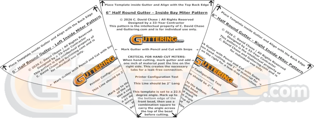
Bay window roofline transitions present a 22.5-degree miter cut angle on each gutter leg — not 45 degrees. The 45-degree label refers to the total corner angle of the bay window geometry, which is bisected into two 22.5-degree cuts at the gutter joint. Fabricating a 45-degree cut on a bay window gutter leg produces a compound gap across the full profile width that cannot be corrected with sealant.
The 22.5-degree cut must be transferred to the gutter metal using a precision template held at fixed geometry. Freehand scribing at this angle produces angular deviation sufficient to create a visible gap at the miter seat. The strip overlap dimension, rivet pattern, and sealant sequence are identical to the 90-degree strip miter specification above.
| Miter Type | Corner Geometry | Cut Angle Per Leg | Strip Overlap (Each Face) | Fastener Type |
|---|---|---|---|---|
| 90° Inside Strip Miter | Standard inside wall corner | 45° | 1 inch minimum | 1/8-inch aluminum pop rivet |
| 90° Outside Strip Miter | Standard outside wall corner | 45° | 1 inch minimum | 1/8-inch aluminum pop rivet |
| 45° Bay Inside Strip Miter | Bay window inside return | 22.5° | 1 inch minimum | 1/8-inch aluminum pop rivet |
| 45° Bay Outside Strip Miter | Bay window outside projection | 22.5° | 1 inch minimum | 1/8-inch aluminum pop rivet |
Section 5 — Sealant Specification and Joint Preparation
The only sealant category appropriate for aluminum gutter miter joints and outlet tube connections is tripolymer or polyurethane formulation rated for metal substrates. Silicone sealants are excluded from this specification. Silicone does not bond reliably to aluminum under thermal cycling conditions and exhibits adhesive failure at the metal bond line within two to three seasonal cycles.
Surface preparation requires removal of all oxidation, oil, and debris from both miter faces using a clean rag and metal adhesion promoter. Sealant applied over an oxidized aluminum surface bonds to the oxidation layer, not the base metal, and delaminates under the first thermal expansion event. Adhesion promoter application followed by a minimum 60-second flash-off period before sealant contact is the correct preparation sequence.
Applied sealant bead width at the miter joint must be sufficient to produce continuous coverage across the full contact surface of the strip overlap without voids. The joint is mechanically clamped or riveted immediately after sealant application. Reliance on hand pressure alone during cure allows thermal movement in the aluminum to open the joint before the sealant achieves full bond strength.
Section 6 — Drip Edge Integration and Back-Bypass Prevention
Drip edge flashing must be installed over the fascia board and under the first course of roofing felt or synthetic underlayment before gutter hanging begins. The drip edge directs roof runoff into the gutter trough rather than behind the gutter back. A gutter installed against a fascia board without drip edge creates a capillary pathway for water migration behind the gutter, producing fascia rot that is not visible from grade level until structural degradation is advanced.
The gutter back must contact the drip edge flashing lip directly. A gap between the gutter back and the drip edge lip exceeding 3/16 inch constitutes a back-bypass condition. Back-bypass produces fascia saturation at a rate proportional to rainfall intensity and is the primary cause of fascia board replacement requirements on systems with otherwise functional gutter hardware.
Execution of the pitch layout, hanger installation, downspout fabrication, and strip miter sequence described above requires a specific set of calibrated hand tools and precision fastening equipment. The complete field-tested guttering tools inventory covering offset aviation snips, rivet guns, hex drivers, torpedo levels, and tripolymer sealant applicators is maintained and updated at the Guttering.com tools reference page.
1 thought on “K-Style Gutter Installation”
Comments are closed.