Fabricate Downspouts Like a Pro: 3×4 A-Elbow Assembly Field Protocol
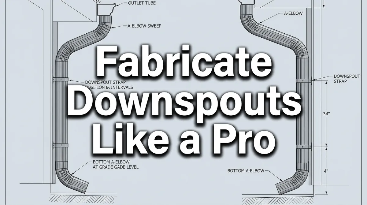
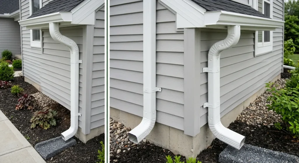
To fabricate downspouts like a pro on a single-story residential installation requires dimensional sequencing across three mechanical subsystems: sweep geometry from outlet to wall, straight section length calculation from wall mark to grade, and strap positioning relative to elbow splice joints. The following 10-step protocol governs 3×4 rectangular aluminum downspout fabrication using A-elbows on a front wall application, per SMACNA Architectural Sheet Metal Manual standards. The technique is scalable to multi-story installations without procedural modification once the single-story sequence is mastered.
Manufacturer Variance and the 1-Inch Cushion Rule
A-elbow dimensional depth varies by manufacturer. A-elbows sourced from different suppliers will produce different sweep geometry outcomes when assembled to the same nominal cut length. A 1-inch dimensional cushion is built into the sweep section cut length at Step 2 to account for this variance. The sweep section will require field trimming of 1 to 1-1/2 inches after test-fitting to achieve flush wall contact at the bottom elbow. This trimming step is a fixed part of the protocol, not an error correction.
Section 1 — Sweep Assembly: Steps 1 Through 4
Step 1 — Measure the Fascia-to-Wall Offset
At the outlet tube position on the gutter, measure horizontally from the front face of the fascia board to the wall surface. This dimension is the fascia-to-wall offset. In the reference tutorial, this measurement is 24 inches. Record this dimension before any cutting begins.
Step 2 — Calculate and Cut the Sweep Section
Subtract 6 inches from the fascia-to-wall offset to produce the nominal sweep section cut length. At 24 inches offset, the nominal cut length is 18 inches. This subtraction accounts for the combined dimensional depth of the two A-elbows that will be attached to each end of the sweep section, plus the 1-inch manufacturer variance cushion.
| Fascia-to-Wall Offset (in) | Subtract (in) | Nominal Sweep Cut Length (in) | Expected Trim After Test-Fit (in) |
|---|---|---|---|
| 18 | 6 | 12 | 1.0 – 1.5 |
| 20 | 6 | 14 | 1.0 – 1.5 |
| 24 | 6 | 18 | 1.0 – 1.5 |
| 28 | 6 | 22 | 1.0 – 1.5 |
| 32 | 6 | 26 | 1.0 – 1.5 |
Step 3 — Crimp and Attach A-Elbows to Sweep Section
Crimp one end of the 18-inch sweep section using a 5-blade downspout crimper. Attach one A-elbow to each end of the sweep section — one elbow at the crimped end, one at the uncrimped end. Elbow orientation is critical at this step. The top elbow must direct the sweep horizontally from the outlet tube toward the wall. The bottom elbow must redirect the assembly to run vertically down the wall face. Male and female end orientation must be confirmed before crimping.
Step 4 — Test-Fit, Trim, and Rivet the Sweep Assembly
Hold the assembled sweep in position from the outlet tube to the wall. The bottom A-elbow will contact the wall surface at a point above the pencil mark location. Trim the sweep section 1 to 1-1/2 inches until the bottom elbow seats flush against the wall without angular tension at either elbow connection. Once the trim dimension is confirmed, rivet each elbow to the sweep section with a minimum of 2 to 4 aluminum pop rivets per connection. No rivets are placed on the bottom face of either elbow.
Section 2 — Wall Mark and Top Strap: Steps 5 and 6
Step 5 — Mark the Wall at the Bottom Elbow Contact Point
With the trimmed and riveted sweep assembly held in its installed position, mark the wall surface with a pencil at the point where the bottom face of the bottom A-elbow contacts the wall. This mark is the dimensional reference for the top strap position and the straight section cut length calculation. The mark must be made before the sweep assembly is lowered from position.
Step 6 — Install the Top Strap 1-1/2 Inches Above the Wall Mark
Attach a 1-inch by 15-inch downspout strap to the wall at a position 1-1/2 inches above the pencil mark. Secure with one fastener centered on the downspout run line. This positioning places the strap over the splice joint between the bottom sweep elbow and the top of the straight downspout section when the assembly is complete, mechanically securing the highest-load connection point in the run. The strap wraps around the finished downspout and fastens to the wall on the opposite side.
Section 3 — Straight Section Calculation: Steps 7 and 8
Step 7 — Measure From the Wall Mark to Grade
Measure vertically from the pencil mark on the wall to the finished grade surface directly below. In the reference tutorial, this dimension is 96 inches. This measurement is the gross straight section length before elbow depth adjustments are applied.
Step 8 — Calculate the Straight Section Cut Length
Apply the following formula to determine the straight section cut length: Wall mark-to-grade measurement minus 6 inches for the bottom elbow depth, plus 3 inches for the combined elbow overlap allowances at both ends. At 96 inches wall-to-grade: 96 − 6 + 3 = 93 inches. Cut the straight downspout section to this dimension.
| Variable | Tutorial Value | Formula Position |
|---|---|---|
| Wall mark to grade | 96 inches | Starting dimension |
| Bottom elbow depth deduction | −6 inches | Subtract |
| Combined overlap allowance | +3 inches | Add |
| Straight section cut length | 93 inches | Result |
This formula applies regardless of wall height. Substitute the actual wall mark-to-grade measurement for the 96-inch tutorial value. The elbow depth deduction and overlap allowance remain constant at −6 inches and +3 inches respectively for standard A-elbow assemblies.
Section 4 — Bottom Elbow and Final Assembly: Steps 9 and 10
Step 9 — Crimp and Attach the Bottom A-Elbow
Crimp the bottom end of the 93-inch straight section. Attach one A-elbow to the crimped bottom end in the discharge orientation — directing water flow away from the foundation perimeter. Secure with a minimum of 2 aluminum pop rivets placed in a diagonal pattern: one rivet at the left rear of the elbow connection, one rivet at the front right. This caddy-corner placement distributes the mechanical load across two orthogonal axes of the connection perimeter, preventing rotation under hydraulic load.
Step 10 — Attach to Sweep, Install Bottom Strap, and Rivet All Connections
Slide the top of the straight section into the bottom elbow of the sweep assembly. Secure the top joint with 2 pop rivets placed at the rear face of the elbow — not the bottom face. Test-fit the full assembly against the wall and mark the wall at the top of the bottom elbow position. Install the bottom strap at this mark with one fastener to the wall.
Attach the top of the sweep assembly to the outlet tube with 2 pop rivets. Wrap both straps around the completed downspout assembly and secure each strap with a minimum of 2 rivets per strap — one rivet at the front face and one rivet at the side face of the strap-to-downspout connection. This dual-axis rivet pattern prevents strap rotation under wind loading and thermal movement.
| Connection Point | Rivet Count | Placement Pattern | Bottom Face Rivet |
|---|---|---|---|
| Outlet tube to sweep top elbow | 2 | Rear face, one per side | ❌ Prohibited |
| Sweep top elbow to sweep section | 2 – 4 | Top sides and wider top face | ❌ Prohibited |
| Sweep bottom elbow to sweep section | 2 – 4 | Top sides and wider top face | ❌ Prohibited |
| Straight section to sweep bottom elbow | 2 | Rear face of elbow at top joint | ❌ Prohibited |
| Straight section to bottom elbow | 2 | Diagonal — left rear and front right | ❌ Prohibited |
| Strap to downspout (each strap) | 2 minimum | Front face + side face | N/A |
Installation Time Standard and Scalability
A correctly sequenced single-story 3×4 downspout installation — from sweep measurement through final strap riveting — is completable in under 15 minutes when all dimensional calculations are completed before the first component is lifted to the wall. The sequence described in Steps 1 through 10 is the invariant framework. Multi-story installations extend the straight section length calculation at Step 8 but do not alter the sweep geometry protocol, the rivet placement rules, or the strap positioning logic.
The 1-inch manufacturer variance cushion at Step 2 applies to every installation regardless of elbow brand. Once the trim dimension for a specific elbow supplier is established through a single test-fit, subsequent installations using the same elbow source can be pre-cut to the trimmed dimension without a test-fit step, further reducing installation time.
This article follows the field specification established in K-Style Gutter Installation — reference that specification for upstream pitch geometry, hanger spacing, and outlet tube placement before beginning downspout fabrication.
Execution of the sweep measurement, straight section calculation, rivet pattern, and strap positioning sequence described above requires a calibrated rivet gun, 5-blade downspout crimper, offset aviation snips, and a hex driver set rated for aluminum substrate work — the complete specialized guttering tools inventory covering every component of the professional downspout fabrication rig is maintained and updated at the Guttering.com tools reference page.
1 thought on “Fabricate Downspouts Like a Pro”
Comments are closed.